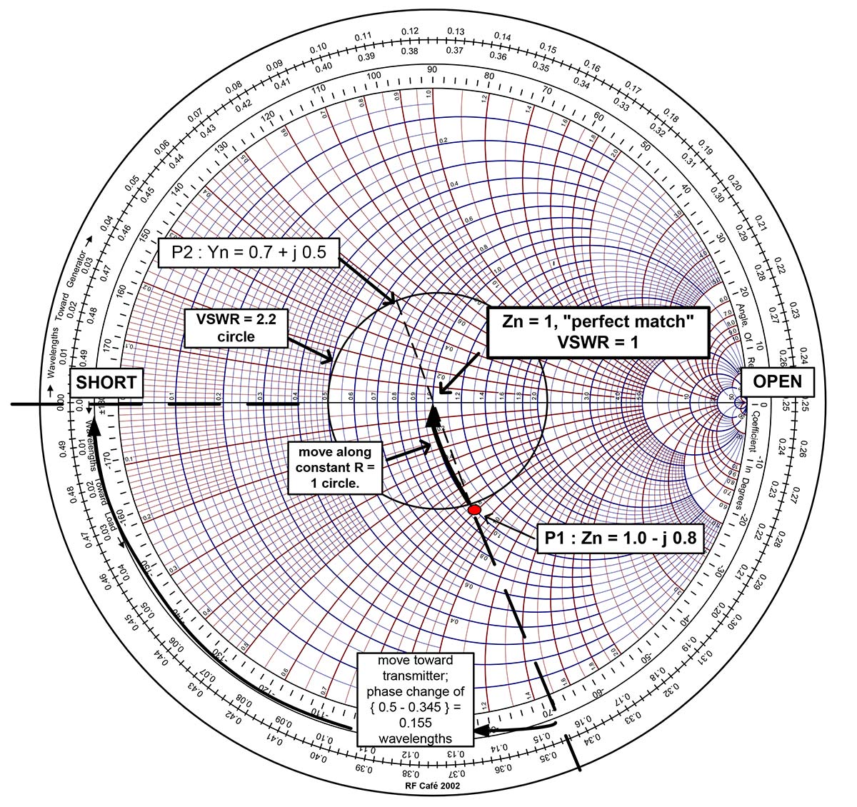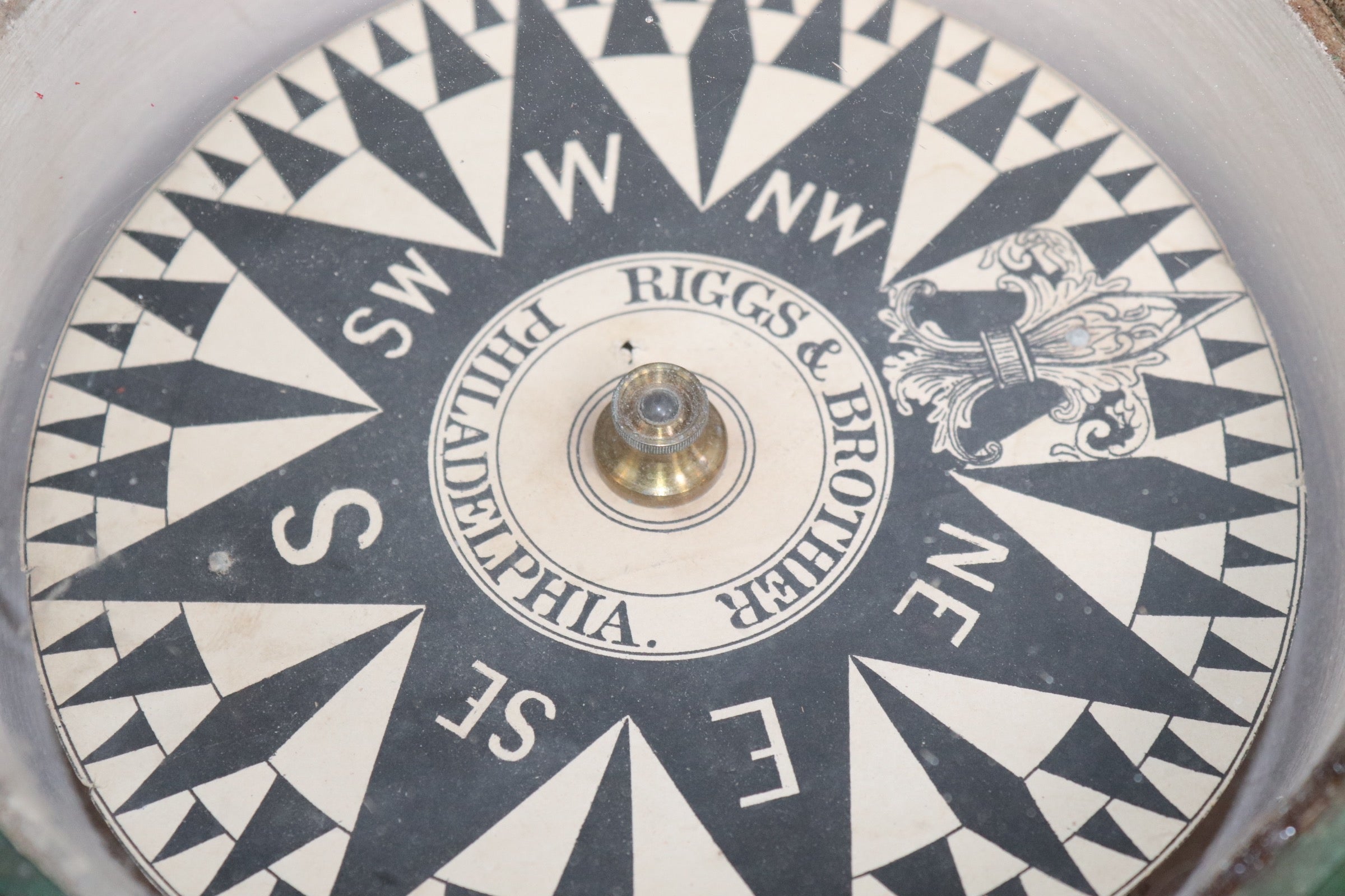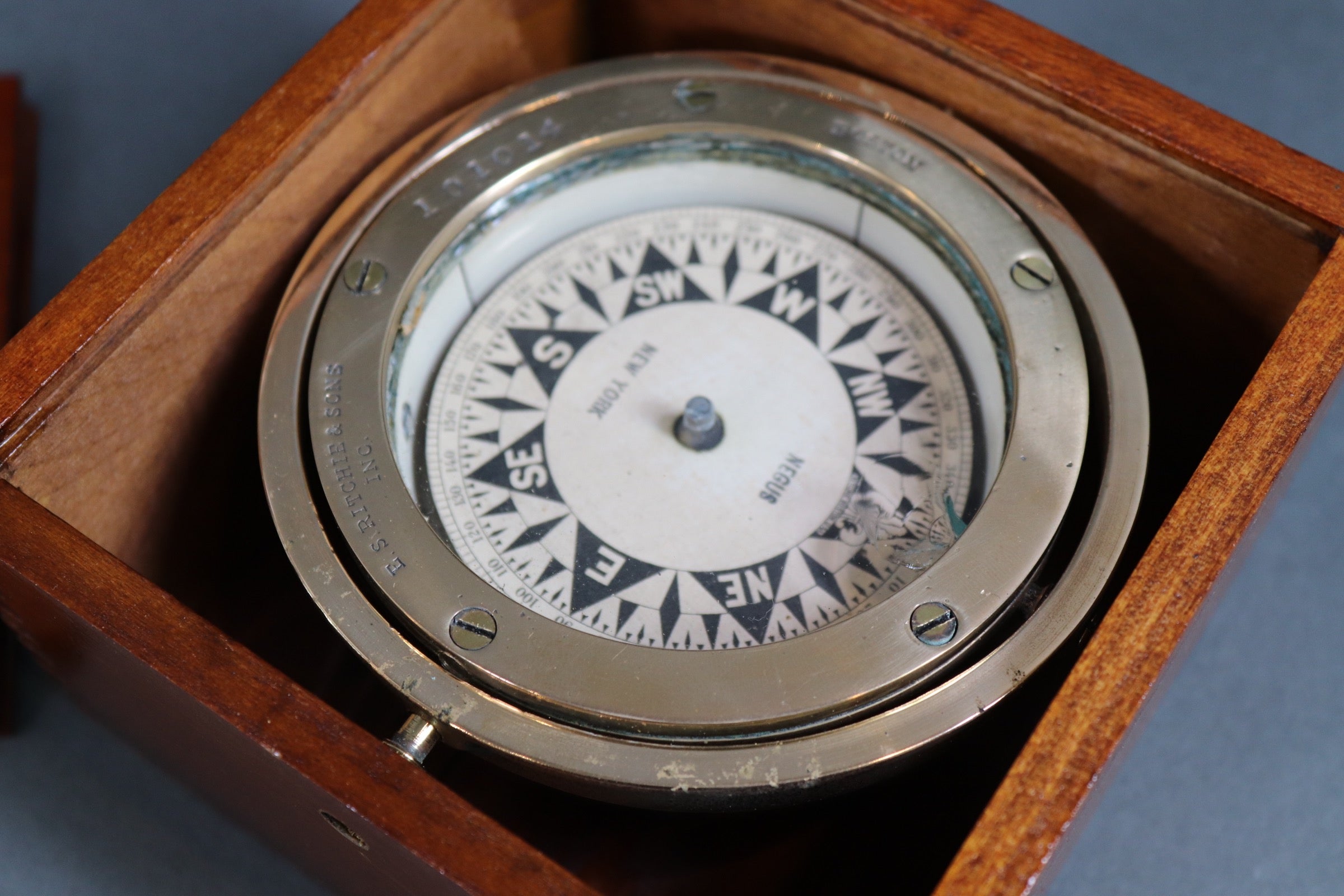
There will be some smith chart examples to follow shortly. Estimate the magnitude and angle of the complex reflection coefficient, 11, using a compass, and by drawing a line from the center of the Smith chart through. The math to follow is very similar to that of the ECE 329 notes, but it is included for your convenience. The Smith Chart The Smith Chart is simply a graphical calculator for computing impedance as a function of re ection coe cient z f() More importantly, many problems can be easily visualized with the Smith Chart This visualization leads to a insight about the behavior of transmission lines All the knowledge is coherently and compactly. Use the mouse or touch to select a point on the Smith chart, representing a pair of complex numbers r (the reflection coefficient) and z (the normalized. Try the original compass for now, no-flair bootlicking statist commie non-degenerate poor anti-consumerism collectivist tax-loving FED-dicksucking fuck.


3) Used to solve problems associated antennas, filters, impedance matching. This might seem a little strange at first, but coordinate systems are arbitrary anyways and also there are situations where we want to attach a transmission line to another transmission line and in those situations the load always stays in the same position so it’s a good choice for the origin. (using char,t ruler, compass, slide rule). We can use this Smith Chart to read off the values for the.

We will define a d-axis that has positive direction pointing from the load to the source where the load is used as the origin. Smith Chart in Figure fig:SCDerscadmimp has impedance circles, and impedance coordinates on it. For the next discussion on quarter and half wave transformers we will need to define a new coordinate system.


 0 kommentar(er)
